14+ hydraulic cylinder diagram
See position diagram position. Whether your application is manufacturing automotive construction agriculture forestry or.

Problem Solving Questions On Fluid Pressure Calculations Depth Density Factors Hydraulic Pressure Systems Igcse Gcse 9 1 Physics Revision Notes
Our concept is to offer our customers a large variety of hydraulic cylinders at reasonable prices and prompt deliveries.

. EP1488941B1 2009-06-03 Airtight coaxial hub to regulate the internal pressure of tyres even when the vehicle is riding. 00 - COMPLETE MACHINE DIAGRAM. They are used to hold the hydraulic oil.
A simple hydraulic schematic showing apparatus for testing the strength of a hydraulic hose splice. Brake master cylinder parts. The master cylinder is a device that converts force usually from the drivers foot into hydraulic pressure.
The reservoir is used to hold the brake fluid. The cylinder is cushioned in the front and rear. Hydraulic cylinders are constructed from high strength steel and.
The purpose of this device is to control the slave cylinders located at the. A simple diagram below helps explain the mechanics of the process -- as fluid enters a chamber more force is applied to push or pull the piston rod in or out of the cylinder and in. Water enters through normally closed solenoid valve 1 and passes through intake flow.
We offer a broad range of replacement cylinders. 86 156 2898 5661. 1 John Deere Hydraulic System Diagram with Parts Details.
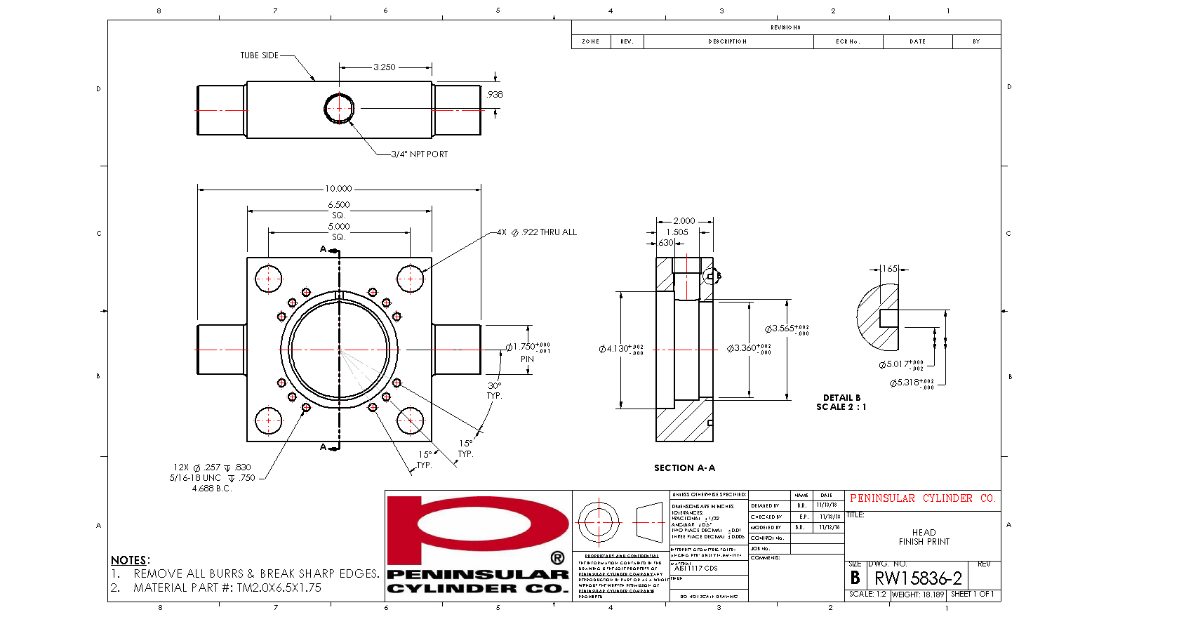
It has cushion adjust and checks in positions 2 4 6 and 8. The ports are -16 SAE and are located In positions 1-5. We offer quality construction on all cylinder models with bore sizes.
The brake master cylinder consists of the following parts-1 Reservoir. Reservoir Oil Tank. They are used to pressurized the hydraulic fluid and force the fluid through the systemThere.
China Hydraulic Cylinder Parts Diagram Manufacture Visit Here to Find the Hydraulic Cylinder Parts Diagram That You are Searching for. Bailey designs manufactures and sources the highest quality hydraulic cylinders available. This hydraulic cylinder has a 3 bore and a 14 stroke with a retracted length of 24-14 and an extended length of 38-14.
It has a filler cap with an air vent and. C-14 - HYDRAULIC CYLINDER LIFT PARTS. US4821624A 1989-04-18 Stroke limiter for hydraulic cylinder.
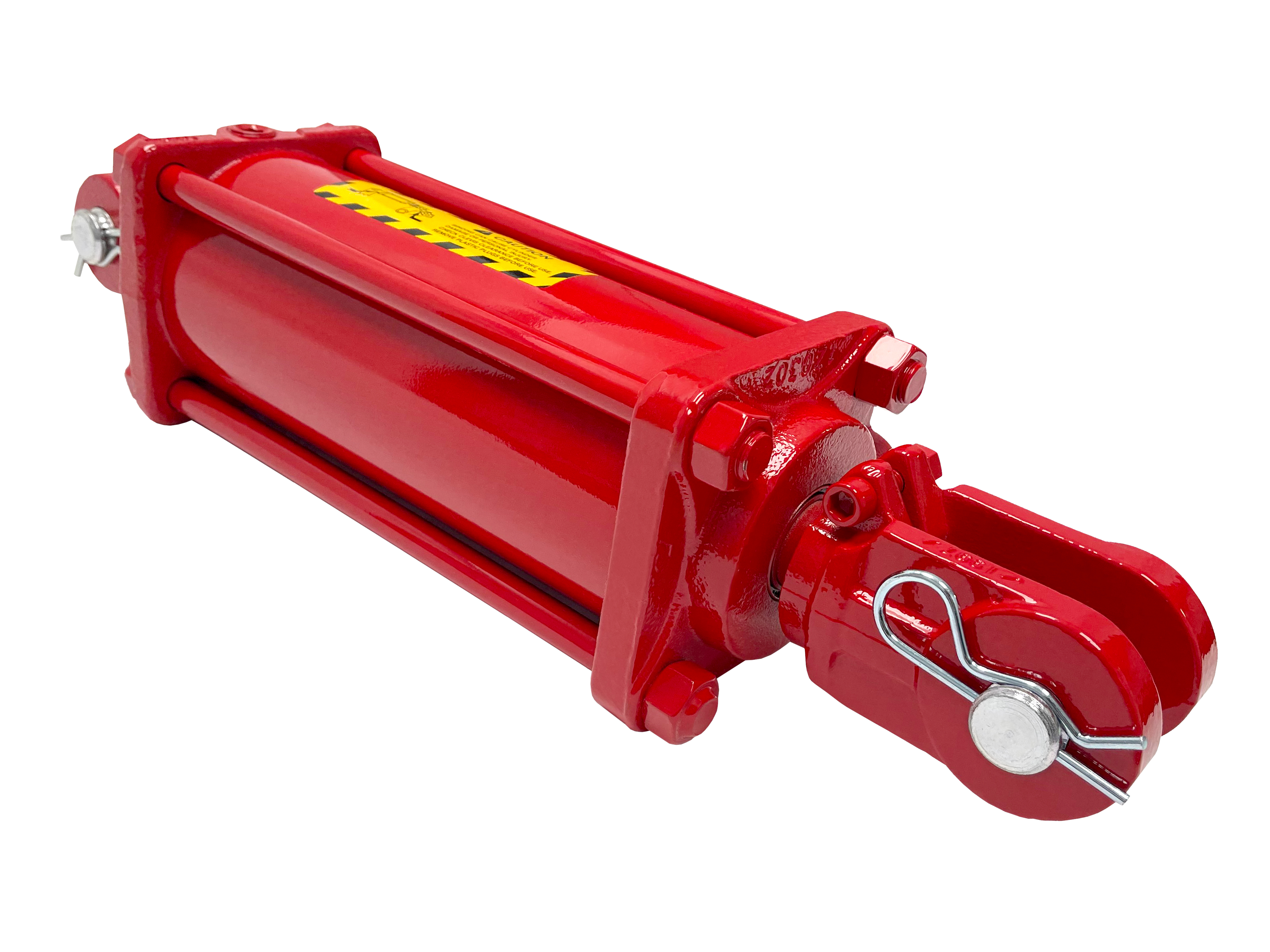
Ag Clevis Tie-rod Cross Tube Swivel Cylinders in stock.
![]()
Installation Location Of Hydraulic Cylinder Download Scientific Diagram

Hydraulic Cylinder An Overview Sciencedirect Topics
Cylinder Repair Hydraulic Air Cylinders 800 526 7968
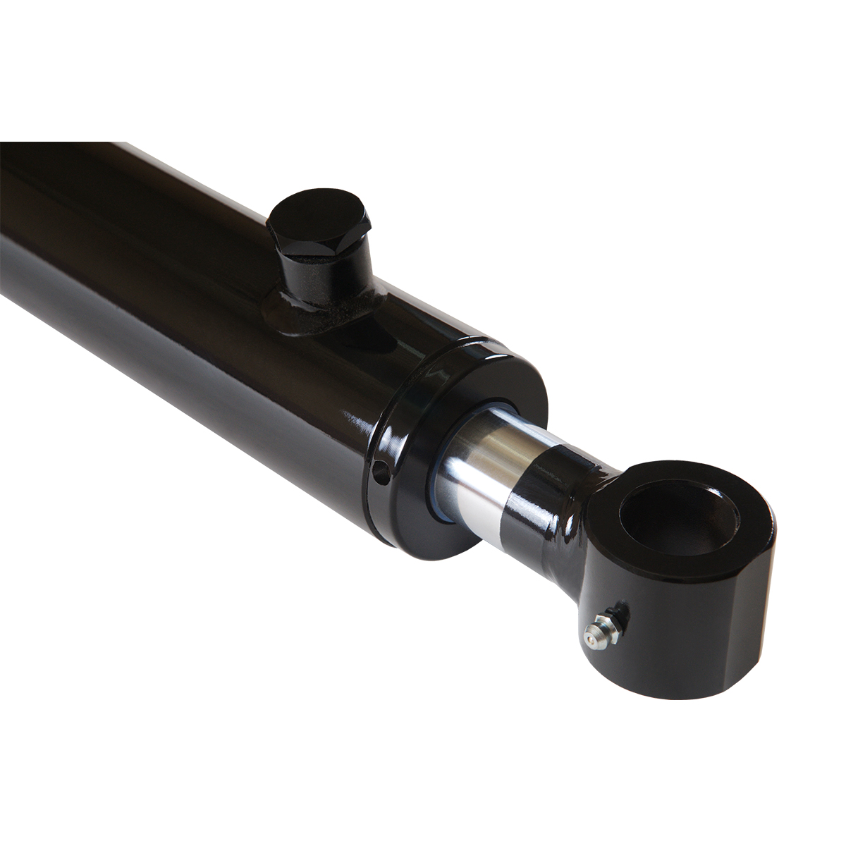
2 Bore X 14 Stroke Hydraulic Cylinder Welded Tang Double Acting Cylinder Magister Hydraulics
Schematic Diagram Of Hydraulic Cylinder Structure Download High Quality Scientific Diagram

Parameters Defining The Position Of One Of The Hydraulic Cylinder Rod Download Scientific Diagram
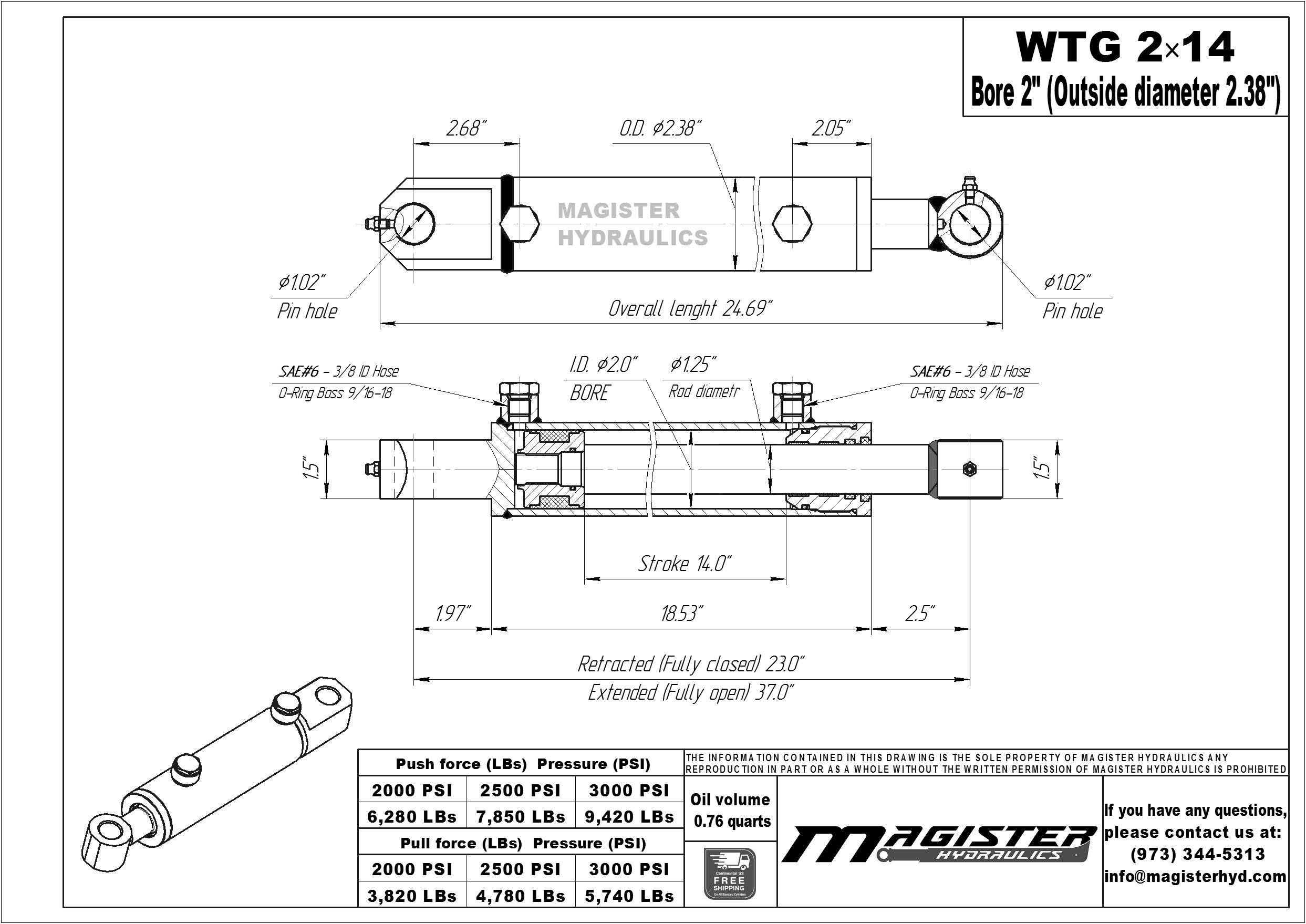
2 Bore X 14 Stroke Hydraulic Cylinder Welded Tang Double Acting Cylinder Magister Hydraulics

Bespoke Hydraulic Cylinders To Specification Steerforth Online
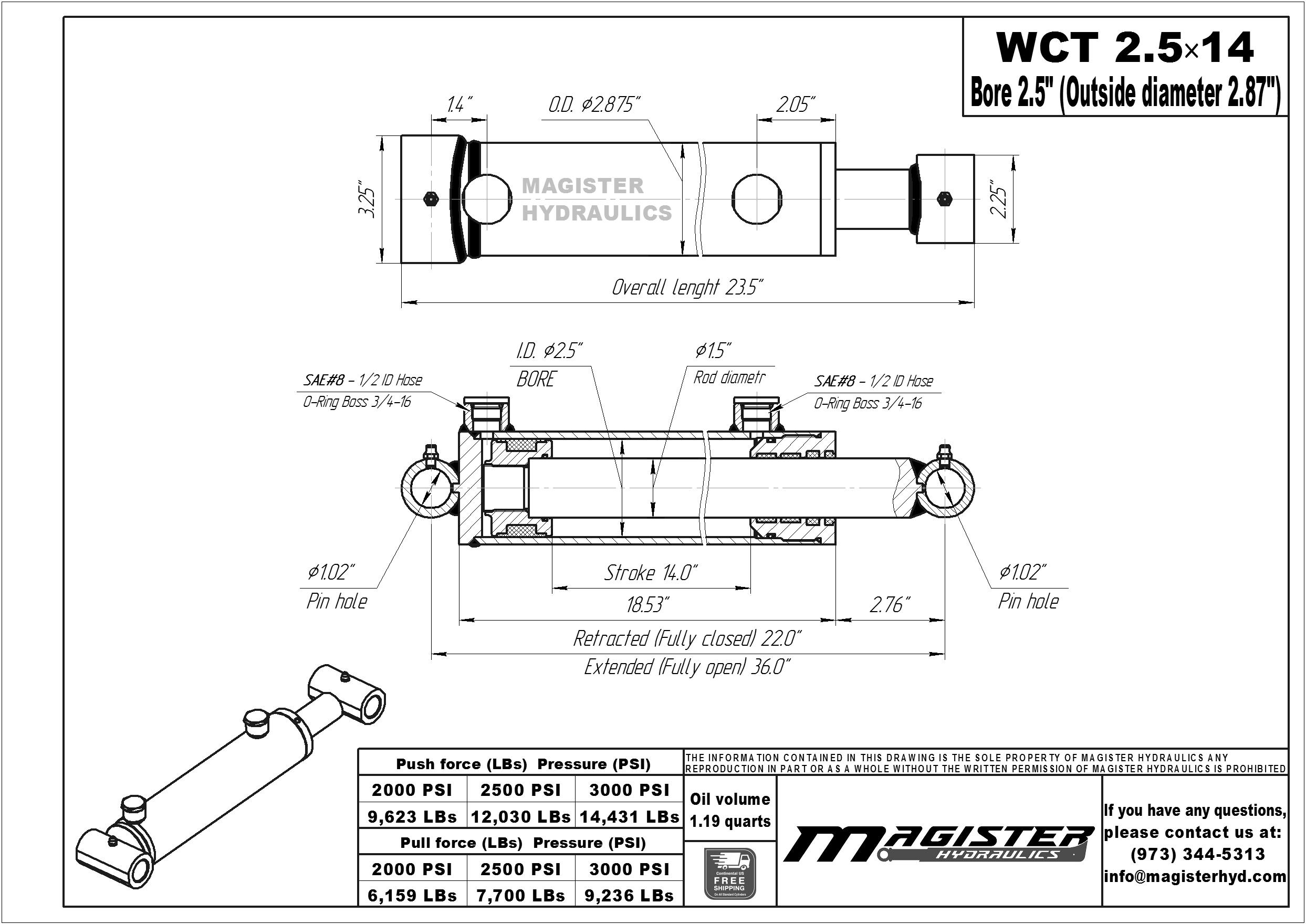
2 5 Bore X 14 Stroke Hydraulic Cylinder Welded Cross Tube Double Acting Cylinder Magister Hydraulics

Hydraulic Cylinder Parts Diagram Quizlet
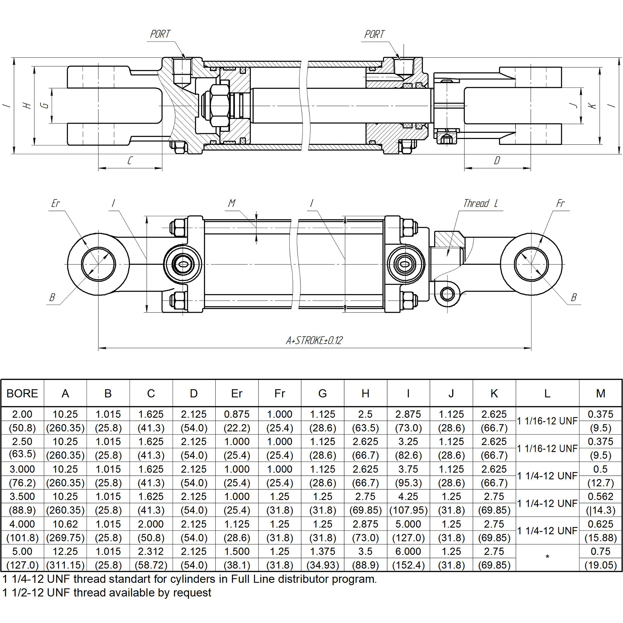
5 Bore X 14 Stroke Cross Hydraulic Cylinder Tie Rod Db Series Cylinder Cross Manufacturing
How Do I Buy A Hydraulic Cylinder

Hydraulic Cylinder An Overview Sciencedirect Topics
5 Bore X 14 Stroke Cross Hydraulic Cylinder Tie Rod Db Series Cylinder Cross Manufacturing

Sumitomo Sh350lc 5 Sh370lhd 5 Hydraulic Excavator Service Text Manual Pdf Download By Heydownloads Issuu
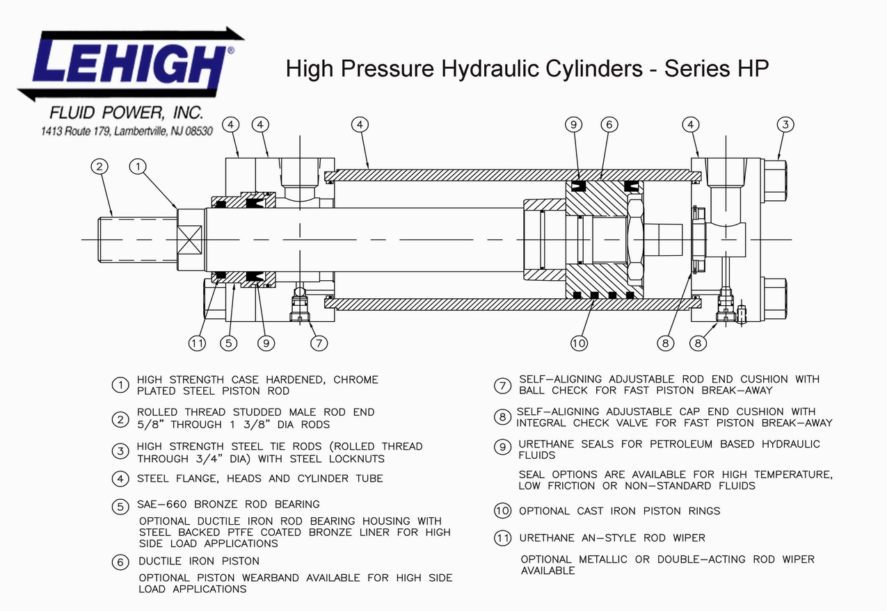
Hydraulic Cylinders Lehigh Fluid Power

Installation Location Of Hydraulic Cylinder Download Scientific Diagram